HANGZHOU SPORTS PARK
NBBJ & CCDI
 |
| Hangzhou
Sports Park, (Hangzhou,
China), Image Courtesy of [NBBJ] |
Project
One will recreate and remodel the Hangzhou Sports Park by using Grasshopper
parametric tools and definitions. The project consists of three main elements,
large petals, small petals and the stage. The project will parametrically
construct these three elements including their structural elements. The final
product will allow the user to change the size of the stadium with maintaining
the proportions of all the petals and their elements. Additionally, it will
allow the user to, parametrically, manipulate the shape and size of all petals. The project will experiment with other
Grasshopper tools, such as Kangaroo 0.99 and 2.00 in association with stress
analysis components. The definition using Kangaroo components will convert
static tensile petals to live tensile petals with anchor points that can
respond to gravity forces and display the stress analysis in real time.
New Method:
Current method, developed by previous students, reconstructed the Hangzhou Sports Park by using a definition based on multiple ellipses with various divisions and points. Each ellipse has a different set of points with certain spacing pattern generated by list tools, such as Item Index, Cull Index and series nodes. The petal shapes were created by interpolated curves using the generated set of points in each ellipse. The previous method can be considered as an efficient method, but it does not cover all the components and elements of the project and the manipulation of the petals is limited.
The new method creates a single parametric model for each type of petal with their structural elements and then array them around the desired shape based on different spacing patterns. The petals of the existing project enclose an ellipse-shape stadium bowl. In order to create a similar ellipse-array in Grasshopper, an ellipse-array definition was created.
Part 1: Large Petal Modeling
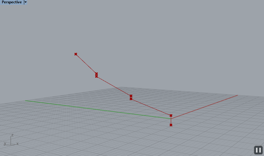
1- 13 control points were created to generate the 2 curves that shape the main profile of the petal. These control points could be used to manipulate the shape of the petal.


2- The 2 generated curves were connected to a Loft node to create the petal surface.


3- Both curves were divided by 20 points to construct horizontal lines between the 2 curves.


4- Petal pedestal was created using a box node at the bottom of the petal.


5- The 2 main truss vertical members were created by 2 curves using multiple control points. The first and last control points are the points of the bottom and top tips of the petal. To find the in-between control points, three steps were made. First, a line between the bottom and top tips of the petal was created and then evaluated using different (t)values to generate new points. Second, the new generated points were used to construct new lines between new points and the control points of the petal profile curves. Third, the new generated lines were evaluated to create in-between control points of the main truss vertical members.


6- The secondary truss vertical members were created by two steps. First, the horizontal lines, created in step 3, were evaluated using different t(value) for each side. Second, the points on each side were interpolated to create the secondary truss vertical members.


7- The truss diagonal and perpendicular lines between the truss main vertical member and the petal profile curve and the secondary vertical member were created by three steps. First, multiple evenly spaced points were created on each curve. Second, a Short node was used to create perpendicular lines between the curves. Third, a combination of Series, Cull Index, Weave and Polyline nodes were used to create the diagonal lines.


8- Pipe nodes with different radiuses were used to convert all the structural lines to pipes.


9- All large petal components were connected to a Merge node and then connected to a Scale node. Using the scale node will allow the user to scale the petal on the X,Y and Z directions.
10- The large petal was connected to a Mirror node to create the double petal.


Part 2: Small Petal Modeling
1- The top and bottom parts of the small petal were created by using similar steps. First, control points were created to generate 1 curve of the main profile. Second, the generated curve was mirrored to complete the profile. Third, the profile curves were connected to a Loft node to create a surface. Fourth, both profile curves were evenly divided to construct horizontal lines between them. Last, profile lines and all horizontal lines were converted to pipes by connecting them to a Pipe node.


Part 3: Seats
1- A polyline was created through multiple points to construct the main profile of the stadium seats. This profile will be arrayed and lofted in later steps.


Part 7: Scale Ratio of Stadium Components
1- A Scale Ratio definition was created for each stadium component. The purpose of these definitions is to make all stadium components always proportionate to the size of the main ellipse. The outcome of all of these definitions were connected to their corresponding Ellipse Array definition.


Part 8: Testing the Stadium Parameters
1- When changing the R1 value of the main ellipse, all stadium components (scale, size, quantities and heights) change accordingly to maintain their proportions to the original design.


2- The control points’ coordinates of the large petals could be used to define and alter their shapes.


3- The control points’ coordinates of the bottom small petals could be used to define and alter their shapes.


4- The control points’ coordinates of the top small petals could be used to define and alter their shapes.


Part 9: Creating Live Tensile Petals with Stress Analysis in Real Time Using Kangaroo 2.00 and Kangaroo 0.99
1- Large Petal is analyzed by connecting the petal mesh to the Kangaroo and Springs definition.
2- Selecting specific points from the naked vertices to be used as anchor points.
3- Unary Force node (Kangaroo 0.99) / Load node (Kangaroo 2.00) are included in the definition to simulate the gravity force.


4- Changing the force value will be reflected in the petal fabric.


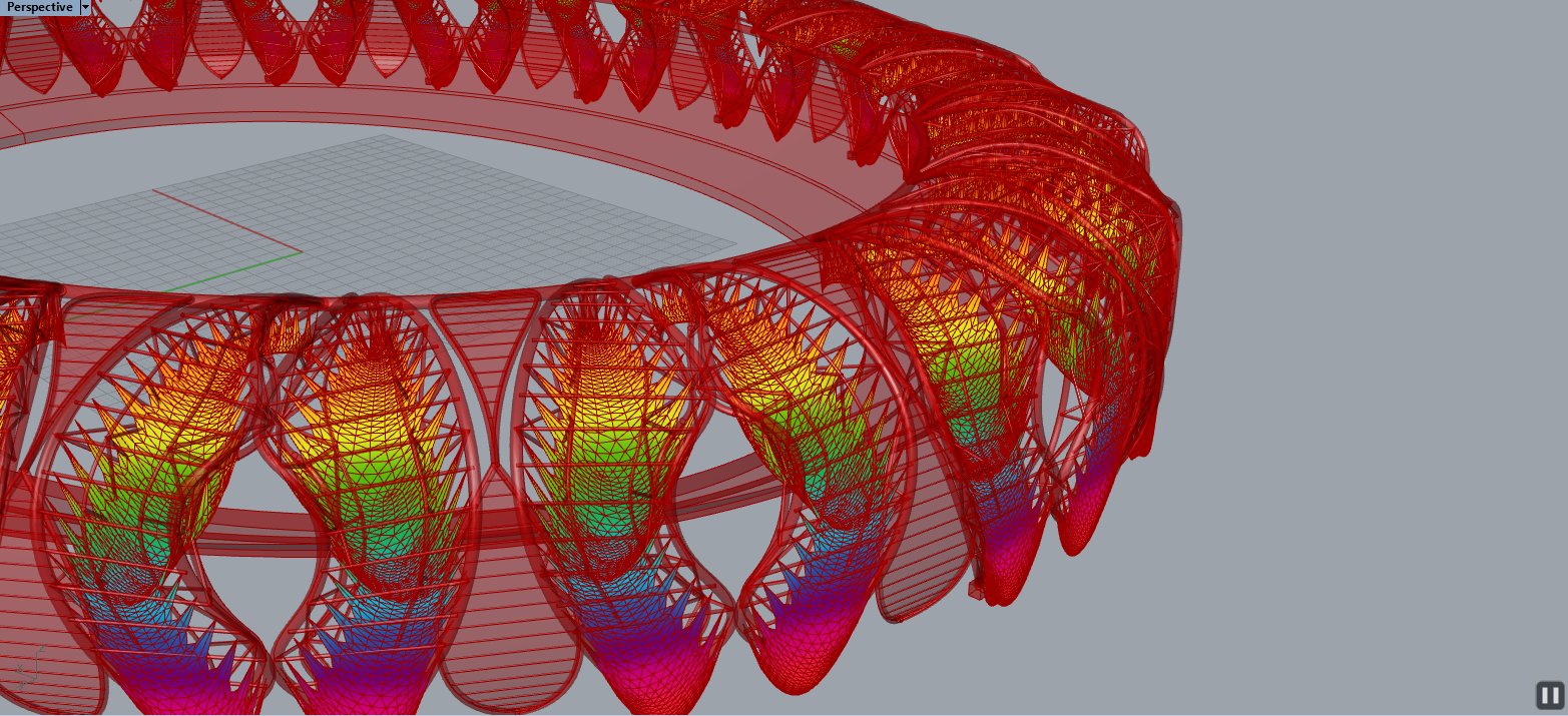
5- The simulated mesh was connected to a Stress Analysis definition represented with multiple color gradient.


6- The same steps were implanted by using Kangaroo 0.99 nodes


Part 10: Connecting Live Tensile Petals with Stress Analysis to the Whole Stadium Definition
1- Live Tensile Petals with Stress Analysis can be connected to the whole stadium through the Kangaroo Switch below.


 |
| Image Courtesy of [NBBJ] |
 |
| Image Courtesy of [NBBJ] |
 |
| Image Courtesy of [NBBJ] |
 |
| Image Courtesy of [NBBJ] |
 |
| Image Courtesy of [NBBJ] |
 |
| Image Courtesy of [NBBJ] |
 |
| Image Courtesy of [NBBJ] |
 |
| Image Courtesy of [NBBJ] |
 |
| Image Courtesy of [NBBJ] |
 |
| Image Courtesy of [NBBJ] |
 | |
|
New Method:
Current method, developed by previous students, reconstructed the Hangzhou Sports Park by using a definition based on multiple ellipses with various divisions and points. Each ellipse has a different set of points with certain spacing pattern generated by list tools, such as Item Index, Cull Index and series nodes. The petal shapes were created by interpolated curves using the generated set of points in each ellipse. The previous method can be considered as an efficient method, but it does not cover all the components and elements of the project and the manipulation of the petals is limited.
 |
| Previous Method Definition |
 | |
|
Part 1: Large Petal Modeling
1- 13 control points were created to generate the 2 curves that shape the main profile of the petal. These control points could be used to manipulate the shape of the petal.
2- The 2 generated curves were connected to a Loft node to create the petal surface.
3- Both curves were divided by 20 points to construct horizontal lines between the 2 curves.
4- Petal pedestal was created using a box node at the bottom of the petal.
6- The secondary truss vertical members were created by two steps. First, the horizontal lines, created in step 3, were evaluated using different t(value) for each side. Second, the points on each side were interpolated to create the secondary truss vertical members.
7- The truss diagonal and perpendicular lines between the truss main vertical member and the petal profile curve and the secondary vertical member were created by three steps. First, multiple evenly spaced points were created on each curve. Second, a Short node was used to create perpendicular lines between the curves. Third, a combination of Series, Cull Index, Weave and Polyline nodes were used to create the diagonal lines.
8- Pipe nodes with different radiuses were used to convert all the structural lines to pipes.
9- All large petal components were connected to a Merge node and then connected to a Scale node. Using the scale node will allow the user to scale the petal on the X,Y and Z directions.
10- The large petal was connected to a Mirror node to create the double petal.
Part 2: Small Petal Modeling
1- The top and bottom parts of the small petal were created by using similar steps. First, control points were created to generate 1 curve of the main profile. Second, the generated curve was mirrored to complete the profile. Third, the profile curves were connected to a Loft node to create a surface. Fourth, both profile curves were evenly divided to construct horizontal lines between them. Last, profile lines and all horizontal lines were converted to pipes by connecting them to a Pipe node.
Part 3: Seats
1- A polyline was created through multiple points to construct the main profile of the stadium seats. This profile will be arrayed and lofted in later steps.
Part 4: Main Ellipse
1- An ellipse node was created to be connected to the ellipse-array definition in later steps. The ellipse is proportionate to the original stadium bowl by defining the scale ratio of R1 to R2.
Part 5: Top Ring
1- A top ring was created by offsetting the main ellipse. Since the top ring goes through the top tips of all petals, its height should be constrained by the height of the top tips. Similarly, the size of the top ring should be proportionate to the size of the main ellipse through a Scale node and conditional statement to determine the scale factor.
Part 6: Ellipse-Array Definition
1- Ellipse-array definition was created because Grasshopper does not have an ellipse-array node. The main ellipse was divided based on another definition that finds the number of petals needed according to the size of the main ellipse and based on a series of conditional statements.
2- A Horizontal Frame node was created for each petal type (large and small) and each Horizontal Frame node is defined by a different set of points on the main ellipse.
3- Horizontal Frame nodes were connected to a Move, Orient and Rotate nodes to complete the array definition.
4- One of the created Horizontal Frame nodes was used to complete the array definition of the seats profile by using a Move, Orient and Loft nodes.
Part 7: Scale Ratio of Stadium Components
1- A Scale Ratio definition was created for each stadium component. The purpose of these definitions is to make all stadium components always proportionate to the size of the main ellipse. The outcome of all of these definitions were connected to their corresponding Ellipse Array definition.
Part 8: Testing the Stadium Parameters
1- When changing the R1 value of the main ellipse, all stadium components (scale, size, quantities and heights) change accordingly to maintain their proportions to the original design.
3- The control points’ coordinates of the bottom small petals could be used to define and alter their shapes.
4- The control points’ coordinates of the top small petals could be used to define and alter their shapes.
Part 9: Creating Live Tensile Petals with Stress Analysis in Real Time Using Kangaroo 2.00 and Kangaroo 0.99
1- Large Petal is analyzed by connecting the petal mesh to the Kangaroo and Springs definition.
2- Selecting specific points from the naked vertices to be used as anchor points.
3- Unary Force node (Kangaroo 0.99) / Load node (Kangaroo 2.00) are included in the definition to simulate the gravity force.
Kangaroo 2.00
4- Changing the force value will be reflected in the petal fabric.
5- The simulated mesh was connected to a Stress Analysis definition represented with multiple color gradient.
6- The same steps were implanted by using Kangaroo 0.99 nodes
Kangaroo 0.99
Part 10: Connecting Live Tensile Petals with Stress Analysis to the Whole Stadium Definition
1- Live Tensile Petals with Stress Analysis can be connected to the whole stadium through the Kangaroo Switch below.
Notes:
1- It was noticed that when connecting Live Tensile Petals with Stress Analysis definition to the whole stadium definition, Grasshopper runs the simulation multiple times (each petal in the stadium will be simulated) which makes Grasshopper consume a lot of time to represent the analysis results.
2- To overcome this problem, the simulated and analyzed petal can be baked and then connected to the stadium definition as shown below.
Comments
Post a Comment