GINZA PLACE
Klein Dytham architecture + TAISEI DESIGN Planners Architects & Engineers

I have chosen Ginza Place to study and apply the parametric techniques that I learned in this course. The project is a commercial building owned by the famous beer company Sapporo. It is located in Tokyo, Japan with an area of 7,350 s.q.m.
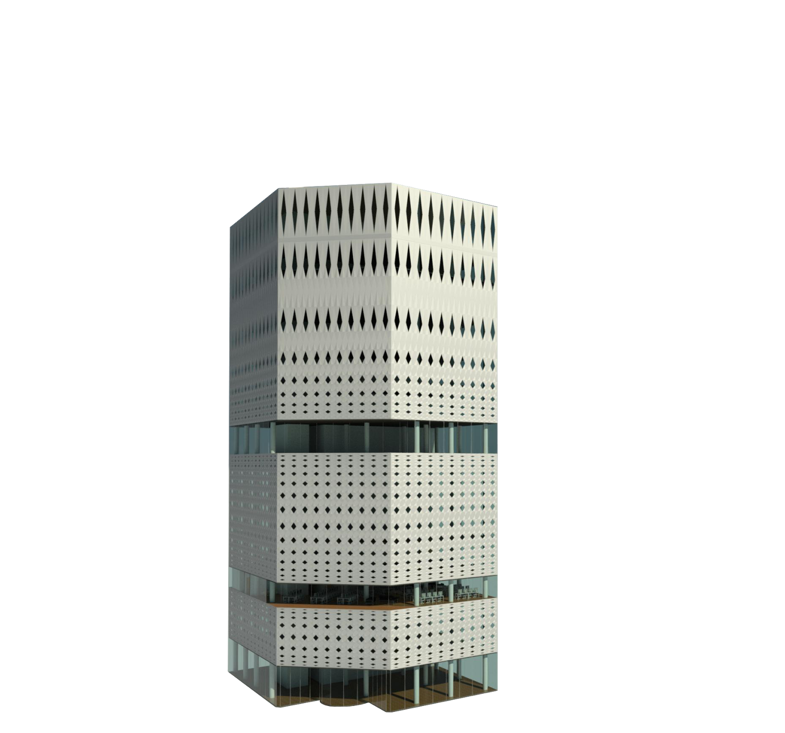
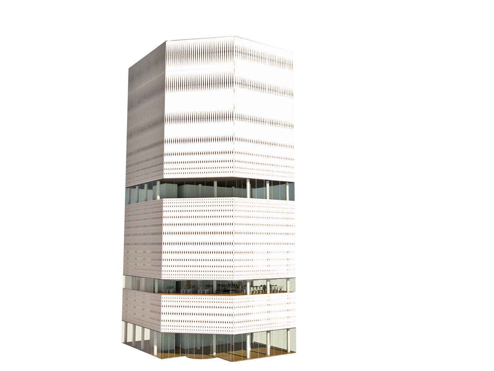
According to the architect, the facade takes its inspiration from sukashibori, a type of open latticework found in traditional Japanese crafts.
Challenges:
The project is very simple considering its
geometry. But it gets very sophisticated at the façade’s level. The size and
the proportion of the pattern (cladding) varies throughout the whole façade. It
gets smaller and narrower at the base and bigger and taller towards the top of
the building.

 |
| Main Elevation |
 |
| 1st Floor Plan |
 |
| 2nd Floor Plan |
 |
 |
| 7th Floor Plan |

Design Intent:
The design intent is to create a parametric
model with the capability of changing its dimensions (width, length and height)
and maintaining the gradient effect of its pattern within the project file. In
addition to that, adding a parameter that would change the size of windows and
cladding.
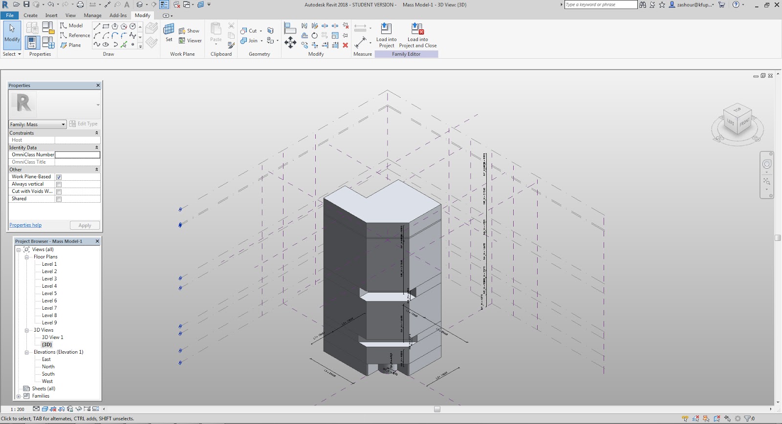
Mass Modeling:
A conceptual mass model was first created according to the existing building with 8 stacked masses. Height, width and length can be parametrically controlled.
1- 9 level lines were created to define the base and top of each mass.
 |
| 1-Conceptual Mass Model (3D View) |
2- Dimension lines were added between each level and then were associated with type parameters to control their heights.
3- 8 reference planes were created, 5 along the X axis and 3 along the Y axis, in order to shape all floor plans.
4- A circle was then created on level-1 in order to shape the revolving door of the main entrance. Then a Start-End-Arc was created using the circle as a reference.
 |
| 2-Conceptual Mass Model (Plan View) |
5- Dimension lines were made to define the spacing between the established reference planes and the radius of the arc.
6- Each dimension line has been associated with a type parameter which uses a formula that maintains the building’s proportions.
L1
L2= L1*1.5
L3= L1*2
M1_R= L1/3.0303
 |
| 3-Family Type Parameters |
7- All floors plans were sketched on their levels based on the reference planes and then extruded according to their heights and starting levels.
8- The dimension height of each extruded mass was also associated with the height parameters created in step (1).
9- Reference lines were added along each level line and then aligned and locked with the top of each mass to avoid clashing masses with each other if any Height parameter was changed.
Pattern & Surface Subdivision
The pattern size is inconsistent throughout the whole building. Pattern size gets smaller at the base of the building and bigger at the top. In some conditions, it gets smaller at the base and top of the mass. In order to control this change, the pattern spacing , horizontal and vertical, should be defined. The pattern used in subdividing patterned-surfaces is Rhomboid.
With defining pattern spacing, the model will be able to maintain the same gradient distribution of the pattern if the values of building size parameters were changed.
Additionally, a type parameter (n) was added to control the size of pattern or units without changing the size of the building.
Horizontal
The pattern is controlled horizontally through adding a type parameter in the V value defined by these formulas:
(Complete formulas are listed in Screenshot-5)
Mass-2
M2_SPACING_LEFT=(L3/370.4mm)/n*1mm
Where n=1
M2_SPACING_MIDDLE=(L_CHAMFER/355mm)/n*1mm
Where n=1
L_CHAMFER=sqrt(L1^2+L1^2)
M2_SPACING_RIGHT=(L2/375 mm)/n*1mm
Where n=1
Vertical
The pattern is controlled vertically through adding horizontal reference lines for each mass ,according to the original facade design. Then, dimension lines were added between reference lines with type parameter defined by these formulas:
(Complete formulas are listed in Screenshot-5)
Mass-2
M2_P1=M2_H*0.008297, Where M2_H is the height of Mass-2
M2_P2= M2_H*0.00938, Where M2_H is the height of Mass-2
M2_P3= M2_H*0.013348, Where M2_H is the height of Mass-2
M2_P4= M2_H*0.01912, Where M2_H is the height of Mass-2
M2_P5= M2_H*0.020924, Where M2_H is the height of Mass-2
M2_P6= M2_H*0.025974, Where M2_H is the height of Mass-2
M2_P7= M2_H*0.03355, Where M2_H is the height of Mass-2
M2_P8= M2_H*0.04329, Where M2_H is the height of Mass-2
M2_P9= M2_H*0.049062, Where M2_H is the height of Mass-2
M2_P10= M2_H*0.054113, Where M2_H is the height of Mass-2
 |
| 4-Elevation View, Shows all reference and dimension lines |
 |
| 5-Family Type Parameters |
 |
| 6-Conceptual Mass Model, subdivision and patterns |
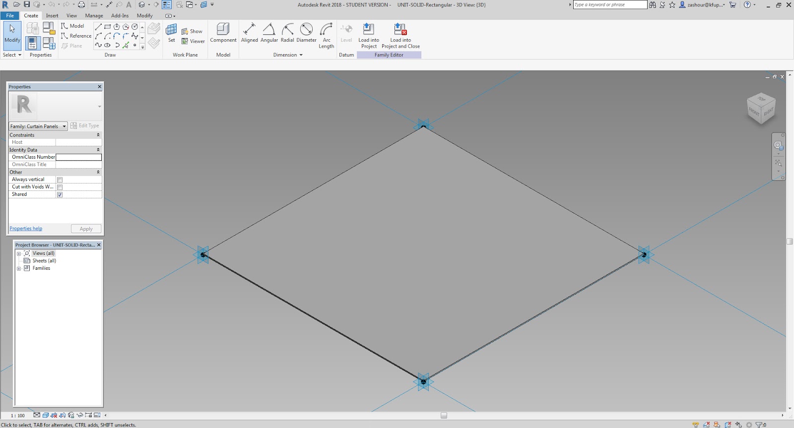
Units Installation
5 units were used to make the building facades. 3 Adaptive Models (Screenshot 7 to 9) and 2 Generic Models-Pattern Based (Screenshot 10 to 11). All models were given material parameters to define their properties at the conceptual mass model and project file.
 |
| 7-Adaptive Model, Window Unit |
 |
| 8-Adaptive Model, Aluminum Cladding Unit |
 |
| 9-Adaptive Model, Aluminum Cladding Half-Unit |
 |
| 10-Generic Model-Pattern Based, Rectangular Windows |
 |
| 11-Generic Model-Pattern Based, Rectangular Aluminum Cladding |
 |
| 12-Conceptual Mass Model, all units installed |
Project File
1. Once the conceptual mass model has been completed, it was loaded into the project file.
2. Level lines were defined in order to create all floors and the roof of the building.
3. Main elevator cores, stairs columns were modeled.
4. Interior portions of the 3rd and 4th floors were modeled.
5. Furniture, fixtures, ceilings were added in the detailed floors.
6. Materials were assigned to building parts.
7. The site and the surrounding buildings were modeled in the project file.
 |
| 13-Project File |
 |
| 1-Street View |
 |
| 2-Façade (Pattern) Details |
 |
| 3-3rd Floor Plan |
 |
| 4-4th Floor Plan |
 |
| 5-Interior Shot, 4th Floor |
 |
| 6-Interior Shot, 3rd Floor |
Changing Paramters
The parametic model has been tested by changing the values of different parameter. Because of the intricate details of the facades, the multiple renders were done in order to see the changes. In Render 7, the height of Mass-4 (m4_H) was increased to 30,000mm. The gradient effect of the pattern has maintained as the original design. In Render 9, The width and length were increased by changing the dimension paramter (L1) to 20,000mm. Similarly, the gradient effect is present.
 |
| 7-Original Tower (Parameter L1=10m) |
 |
| 8-Taller (Parameter M4_H=30m) |
 |
| 9-Wider (Parameter L1=20m) |
In Render 11, the size of patterns has increased by changing the (n) value from 1 (default) to 2.5.
While in Render 12, the (n) value was set at 0.5 to create smaller units. The gradient effect has maintained in both trials.
 |
| 10-Original Tower (Original Window Size, n=1) |
 |
| 11-Original Tower (Bigger Windows, n=2.5) |
 |
| 12-Original Tower (Smaller Windows, n=0.5) |
Note:
Due to the number of parameters and units used in the model, any value change in these parameters will result into a lengthy processing time (10 mins -35 mins).
Conclusion:
In conclusion, the exercise gave me a better understanding of the software capabilities and its limitations. In addition to the design intent of this project, I wanted to make a parametric model with the capability of changing the units’ shape that compose the building façade within the project file and not at the conceptual mass level. But with the limitation of the software, the only way to do that is through going back to the conceptual mass file.
I am looking forward to expand the parametric capabilities of Revit by using Dynamo in the next session of this semester.
REFERENCES
1- https://www.archdaily.com/879524/ginza-place-klein-dytham-architecture
Comments
Post a Comment